
Articles
Energy Efficient Motorsport - a new Alternative Fuel Equivalence Strategy
Author: Roland Ermers
Source: Ricardo Ltd
Publication Date: 1st June 2006
ABSTRACT
This paper presents a project undertaken by Ricardo and the Energy Efficient Motorsport (EEMS) working group in the UK. The purpose of this project is to develop a method to encourage fuel efficiency in motorsport and enable vehicles running different types of fuels to race on a competitive basis without having to set up a complex set of rules for every application and while maintaining exciting racing for both teams and spectators.
Motorsport technologies typically focus on maximum vehicle performance as their prime criteria for optimisation. In this respect they have begun to diverge from the primary technological goal of road car development, which is now focussed around improvement of efficiency and fuel economy. In this paper, a method is proposed whereby the two goals can be combined, allowing technology flow between road cars and racing cars, making participation more attractive for vehicle manufacturers and at the same time improving the environmental credentials of motor racing.
The basis of the proposed method is to cap the instantaneous fuel flow energy to the engine to a maximum value. In this way the race car developers are encouraged to improve the efficiency of the powertrain in order to extract the maximum useable power from the amount of fuel allowed.
A method of implementation was found in the form of an inline fuel flow meter that allows monitoring of fuel flow to the engine. Vehicles will need to be recalibrated to run to a fuel flow limit instead of an air flow limit imposed by an air restrictor used in most race series today.
Fuel flow limits can be defined for various fuels based on the net heat of combustion of the fuel, so that all vehicles racing in one series have the same maximum energy flow to the engine regardless of fuels used.
A system to monitor fuel flow was designed and tested in 2005 on a British Touring Car Championship (BTCC) vehicle running a mixture of ethanol and gasoline. The system consists of an inline turbine flow meter measuring volumetric fuel flow. Measured fuel flow was validated against fuel injection data from the ECU and showed a good correlation.
INTRODUCTION
Fuel efficiency and alternative fuels are receiving increased focus in motorsport. This study, undertaken by Ricardo UK, Ltd, has been commissioned by the Energy Efficient Motorsport (EEMS) Project Team of Motorsport Development UK (MDUK) with the objective to develop and test a methodology that makes it possible to encourage fuel efficiency and alternative fuels usage in existing racing formulae.
In order to limit vehicle speeds to safe levels and to preserve competitive racing, currently many racing series specify maximum engine displacement, maximum boost levels, artificial engine speed limits and/or the use of a restricting orifice in the air induction system. All these measures have in common that they restrict power output by restricting the air flow to the engine. If we want to develop a method that encourages fuel efficiency in racing we need to steer away from air restriction and restrict fuel flow instead.
Fuel efficiency in racing is not new. Indeed, in endurance racing where refuelling costs valuable time fuel efficiency is a significant contributor to success. Equivalence between various fuels can be established by defining maximum fuel tank sizes based on energy content rather than volume and by ensuring that time lost for a complete refill is similar for all fuels.
Specifying fuel tank sizes for sprint races will only encourage fuel efficiency if the maximum amount of fuel allowed is less than what is required to cover the race distance at full performance. This method works well for economy challenges, but is not applicable for existing sprint race formulae where spectators come to watch competitors racing at the limit of performance.
The current study was motivated by recognising the need for a method that restricts engine power by limiting fuel flow and by doing so creating an incentive for the competitor to extract maximum power from the limited fuel flow, encouraging development of fuel efficient engines, while leaving the competitors free to race.
Fuels like bio-ethanol have a lower net heat of combustion than gasoline resulting in a higher fuel requirement for similar performance. By basing the fuel flow limit on the energy content of the fuel it is possible to define regulations that allow vehicles using different fuels to compete on an equivalent basis. The following table shows properties of various fuels. Typical values are given when the fuel is a mixture of various components, like gasoline, Diesel and biodiesel.
|
Density @20°C [kg/m3] |
Net heat of combustion [MJ/kg] |
Energy density [MJ/l] |
Relative volume [%] (*1) |
| Gasoline (*2) |
765 |
43 |
33 |
100 |
| E85 (*3) |
780 |
30 |
24 |
139 |
| Methanol |
791 |
20 |
16 |
210 |
| Diesel (*4) |
850 |
43 |
36 |
91 |
| Biodiesel (RME) (*5) |
880 |
32 |
28 |
116 |
| Propane @8bar (*6) |
500 |
46 |
23 |
142 |
| Methane (*7) @200 bar |
166 |
50 |
8.3 |
396 |
Table 1. Typical fuel properties
- 1: Tank volume required for same energy content as 100l gasoline
- 2: Typical high octane racing gasoline
- 3: 85 vol.% ethanol and 15 vol.% gasoline
- 4: Typical pump Diesel fuel
- 5: RME: Rapeseed Methyl Ester
- 6: Typical component of LPG, stored as a liquid
- 7: Typical component of compressed natural gas, stored as a gas
DEVELOPMENT OF A METHODOLOGY
The first part of the study consisted of a feasibility study with the objective to propose and review possible methods for fuel flow limitation. The most promising methods were investigated further, these included:
- Restricting orifice in fuel line
- Fuel line flow measurement
- Using calibrated injectors, while monitoring fuel rail pressure, injector pulse width and engine speed
These methods were reviewed in conjunction with motorsport regulators, major UK race engine manufacturers and OEMs for:
- Ease of implementation
- Ease of policing
- Reliability
- Accuracy
- Cost
An additional boundary condition was that the method had to work for a variety of fuels, including gasoline, Diesel, biodiesel, ethanol, methanol, LPG (Liquefied Petrol Gas) and CNG (Compressed Natural Gas).
RESTRICTING ORIFICE IN FUEL LINE
Fuel flow to the engine can be physically restricted by placing an orifice in the fuel line between fuel tank and injectors. When the fuel system consists of a fuel return line that bleeds fuel back to the tank the fuel system must be redesigned so that the return line returns fuel to a point downstream of the orifice in the fuel feed.
It is acknowledged that bleeding return fuel back to the fuel line instead of the fuel tank can result in insufficient cooling of the fuel and that additional measures such as fuel radiators may be required to avoid unacceptably high fuel temperatures.
Figure 1 shows a schematic cut-away of a fuel line with an orifice
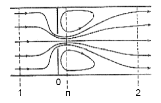
Figure 1. Schematic of fluid flow through an orifice
Principle of flow limitation using an orifice for liquid fuels
Maximum flow of a liquid fuel through a narrow orifice is dependent on pressure drop over the orifice and can be described by a derivation of Bernoulli’s law in the form of [1]:
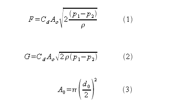
where
Subscripts 0, 1 and 2 refer to locations outlined in Figure 1. The discharge coefficient is a function of fluid properties and geometry of the orifice.
The position of the orifice in the fuel system is an important factor for the pressure downstream and upstream of the orifice and determines fuel flow limitation for a given orifice size and fuel properties.
When the orifice is placed between the fuel pump and the injectors the pressure upstream of the orifice (p1) is dependent on the pressure at pump outlet; the pressure downstream of the orifice (p2) is defined by the injection pressure and pressure losses in the fuel system. The maximum fuel delivery of the fuel pump can be derived by plotting the fuel pump characteristic curve and the system curve of the fuel line with orifice. Both are fuel system dependent, meaning different orifice sizes need to be defined for different fuel systems.
When the orifice is placed between the fuel tank and fuel pump the fuel pressure upstream (p1) is equal to the fuel pressure in the fuel tank, which is typically equal to or lower than atmospheric pressure in fuel tanks for liquids; the pressure downstream the orifice (p2) is a function of fuel flow, and hence the fuel pump, and will decrease with increasing flow until vapour pressure of the fuel is reached. Fuel flow through the orifice will be limited by choking cavitation. Cavitation can cause damage to components downstream of the orifice such as fuel pump and fuel lines.
Principle of flow limitation using an orifice for gaseous fuels
The relation between volume flow and pressure drop over an orifice for gases can be described by another derivation of Bernoulli’s law, in the form of [2]:
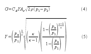
where
| Y = Expansion factor |
[-] |
| κ = Ratio of specific heats |
[-] |
| cp = Heat capacity at constant pressure |
[J/kg.K] |
| cv = Heat capacity at constant volume |
[J/kg.K] |
The maximum gas flow through an orifice can be calculated by combining equations 4, 5 and 6 and differentiation; it follows that maximum flow occurs at a critical value of pn/p1 [2]:

So for given orifice properties and gas properties (density and ratio of specific heats), the maximum mass flow rate only depends on the gas pressure upstream of the orifice (p1). This pressure is typically equal to the fuel pressure in the tank when the orifice is placed in the fuel line between the fuel tank and the pressure reduction valve. Fuel pressure in the fuel tank for gaseous fuels is not constant but depends on the fill state of the tank.
When CNG is used as a fuel, the orifice could be placed downstream of the pressure reduction valve; the pressure reduction valve would need to be policed by the regulator.
The fuel in LPG systems using gaseous (vapour) injection is gaseous downstream of the pressure reduction valve (evaporator), meaning that the equations for gaseous fuels apply. Newer LPG systems based on liquid injection use a fuel pump and no evaporator, the fuel remains in liquid form until the injector and fuel flow limitation is described by equations 1-3.
FUEL LINE FLOW MEASUREMENT
The second option that was investigated was monitoring of the fuel flow between the fuel tank and engine. With this method the competitor must ensure that the fuel flow to the engine does not exceed a predefined limit.
Compliance is monitored by the regulator using a fuel flow measuring device in combination with a data logger in much the same way that engine speed limitations are enforced in several current racing formulae.
The competitor can control fuel consumption of the vehicle by means of an advanced engine calibration using feedback of the fuel flow measuring device.
When the fuel system consists of a fuel feed and return line the net fuel flow to the engine can be derived by measuring fuel flow in both the fuel feed and return. Care must be taken when the return flow is significant, for example with Diesel fuel systems, that subtracting two large numbers to derive a small net flow can result in significant error build up. An alternative is to use one fuel flow measuring device in the fuel feed and redesign the fuel system so that the return line returns fuel to a point downstream of the fuel flow meter.
The flow rate of liquid fuels can be measured using a turbine flow meter. Turbine flow meters measure the rate of flow in a pipe via a freely suspended, bladed rotor that spins as the fluid passes through its blades. The rotational speed of the rotor is proportional to volumetric flow rate of the fluid and can be sensed by magnetic pick up.
The rotational speed of the rotor also depends upon fluid properties; the most important one is the kinematic viscosity. Since kinematic viscosity of a liquid is a function of temperature a change in temperature will have an effect on the flow measurement. Temperature also has a small, but not insignificant effect on the density of the liquid, which is an important parameter when converting a volume flow to a mass flow.
Temperature effects can be accounted for by monitoring the fuel temperature close to the fuel flow meter and by placing the fuel flow meter at a location in the vehicle where the temperature is relatively constant. The flow rate of gaseous fuels can also be measured using a turbine flow meter. The density of a gas depends much more on temperature as is the case with liquid fuels. It is therefore recommended for gas flow rate measurements to use a mass flow meter, such as a coriolis type flow meter.
For accurate flow measurements with a turbine flow meter it is recommended that a straight pipe with constant diameter with length of at least 10 diameters upstream and 5 diameters downstream is provided. Due to space restraints and to minimise temperature effects the fuel flow meter is best not placed in the engine bay.
In order to encourage fuel efficient racing the regulator must specify and police that no fuel can be accumulated between the fuel flow meter and the engine, which could be released to enable a higher than measured fuel flow for a short period of time.
CALIBRATED INJECTORS IN COMBINATION WITH FUEL PARAMETER MONITORING
The amount of fuel injected in the cylinders per engine cycle is limited by the maximum flow capability of the injectors.
Other parameters that determine maximum fuel flow are fuel pressure, injector pulse width and engine speed. If the injectors are calibrated and maximum static flow is known to the regulator the regulator can set limits for fuel pressure and injector pulse width for a given engine speed.
Controlling the injector pulse width can be done in the ECU, but only if the ECU is regulated by the race series; alternatively the injector pulse width can be monitored, but this requires very advanced and expensive logging equipment due to short opening times of injectors. This is especially the case for Diesel engines.
Changes in the opening and closing time of the injector as a result of effects such as battery voltage fluctuation should be accounted for, and for Diesel engines the properties of the injector drivers are known to have an effect on fuel delivery.
It must be noted that Diesel engines have a limited time window during the engine cycle in which to inject and burn fuel efficiently. Injection of fuel outside this window does not improve performance of the engine, but the vehicle would produce visible smoke or quickly fill its particulate trap (if one is fitted), increasing the back pressure and reducing performance. Due to this physical limitation it would be possible to limit fuel flow for Diesel engines by controlling only the static flow of the injectors and maximum allowed fuel pressure.
For spark ignited engines the maximum duty cycle of the injectors is theoretically 100%, but in practice this is smaller. Due to the required opening and closing time of fuel injectors, a result of inertia of moving parts, it is difficult to correctly control fuel flow close to 100% duty cycle.. Leaving the maximum injector pulse width free to the competitors whilst controlling the static injector flow and fuel pressure would stimulate the development of injectors with higher maximum duty cycles, a valid engineering exercise but not necessarily in the interest of fuel efficient motorsport.
Calibration and policing of fuel injectors of all competitors is a time consuming task, where allowing only a limited number of calibrated injector types was perceived as too much of a restriction by the major UK race engine manufacturers.
CONCLUSION
Fuel flow limitation by means of an orifice in the fuel line is not a trivial solution. Depending on the position of the orifice in the fuel line one would need to define different orifice sizes for various fuel systems or limit fuel flow by choking cavitation, which can seriously harm the fuel system.
It was found that motorsport regulators and engine manufacturers generally prefer a method that involves monitoring and enforcement rather than a physical restriction.
A potential method for controlling fuel flow to the engine is by monitoring using a fuel flow meter. This method has the advantage that it is generic to all liquid fuels and only requires minor modifications to the fuel system. There is no significant physical restriction of the fuel flow; it is the responsibility of the competitor not to exceed a predefined maximum flow limit. Feedback from the fuel flow meter can be used as an input to the engine management system to control the fuel flow. It is noted that the fuel temperature can have an effect on measurement of volumetric flow and on the density of the fuel.
Fuel flow control by means of calibrated injectors and monitoring of injector pulse width and fuel pressure is more complex than the use of a fuel flow meter and requires more advanced data logging equipment.
Calibration and policing of fuel injectors is a time consuming exercise.
TESTING OF FUEL FLOW METER
A device for measuring volumetric flow rates was tested for applicability as a fuel flow meter in a race vehicle under racing conditions.
The tested flow meter was a Flowtech FT4-8 turbine flow meter with amplified pickoff with the following specifications:
| Manufacturer |
FTI Flow Technology, Inc |
| Normal flow range [litres/min] |
0.95 – 9.5 |
| Linearity [%] |
±0.05 |
| Pickoff |
Amplified modulated carrier (RF) |
| Output level [VDC] |
0-5 |
| Frequency range [Hz] |
10 - 3200 |
Table 2. Specifications FT4-8AEXS BLEAH4 flow meter
CALIBRATION
The fuel flow meter was calibrated by the supplier using a standard calibration fluid according to specification MIL-PRF-7024E.
The viscosity of this calibration fluid was 1.30cSt at 22.2°C. The viscosities of the fuels considered in this part of the study are summarised in the following table:
|
Hiperflo 250 |
E85 |
EN590 Diesel |
| Viscosity at 40°C [cSt] |
0.46 |
0.91 |
3 |
Table 3. Viscosities of tested fuels
Hiperflo 250 is a gasoline fuel used in the British Touring Car Championship. E85 is a mixture of 85 volume % bioethanol and 15 volume % Hiperflo 250. The EN590 Diesel fuel is a standard BP pump Diesel fuel.
The viscosity of the fluid can have an important effect on the behaviour of the turbine flow meter. In order to assess the effect of the fuel properties on the calibration the fuel flow meter was recalibrated for Hiperflo 250, E85 and EN590 Diesel fuel. Results of the calibrations are shown in Figure 2.
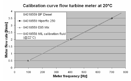
Figure 2. Calibration of flow sensor for various fuels
Due to the linearity of the meter response it is possible to derive a first order curve fit for the meter response for each fuel and compare the calculated fuel flows for a given meter frequency, as shown in Table 4.
|
Flow rate [l/min] |
| Frequency [Hz] |
MIL calibration fluid |
Hiperflo 250 |
E85 |
EN590 Diesel |
| 100 |
0.498 |
0.500 |
0.496 |
0.516 |
| 200 |
1.001 |
0.998 |
0.994 |
1.013 |
| 300 |
1.504 |
1.495 |
1.493 |
1.509 |
| 400 |
2.007 |
1.993 |
1.991 |
2.005 |
| 500 |
2.510 |
2.490 |
2.489 |
2.501 |
| 600 |
3.013 |
2.988 |
2.988 |
2.997 |
Table 4. Derived flow rate from calibration curve for various fuels
The effect of the different fuels properties of the fuels compared to the calibration fluid can be quantified by comparing the derived flow rates for the various fuels with the flow rate of the MIL calibration fluid for the same meter frequency. The next table shows the deviation of derived fuel flow rate using the MIL calibration fluid as a reference (100%):
|
Deviation of derived flow rate using MIL calibration fluid as a reference [%] |
| Frequency [Hz] |
Hiperflo 250 |
E85 |
EN590 Diesel |
| 100 |
0.37 |
0.41 |
3.68 |
| 200 |
0.36 |
0.67 |
1.15 |
| 300 |
0.61 |
0.76 |
0.31 |
| 400 |
0.73 |
0.80 |
0.11 |
| 500 |
0.80 |
0.83 |
0.36 |
| 600 |
0.85 |
0.85 |
0.53 |
Table 5. Comparison of derived fuel flow rates in percentage deviation from fuel flow rate of MIL calibration fluid
As shown in Table 5 the deviation of derived fuel flow rate for the various fuels is less than 1% in most cases, despite the differences in kinematic viscosity.
INSTALLATION
The fuel flow meter was installed in a BTCC Vauxhall Astra.
The test vehicle was running a mixture of bio-ethanol and gasoline. The fuel system of the test vehicle was of the returnless type.
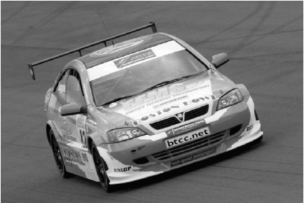
Figure 3. BTCC Vauxhall Astra test vehicle
The fuel flow meter was installed in the fuel line just downstream of the fuel tank and fuel pump behind the driver’s seat. The fuel flow meter was mounted to the car body with Anti-Vibration mounts to minimise possible influence of vibrations of the chassis on the fuel flow measurements.
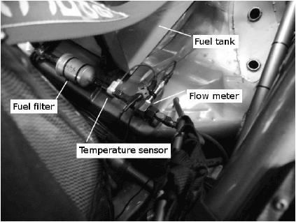
Figure 4. Installation of fuel filter, temperature sensor and flow
A temperature sensor was installed close to the fuel flow meter. The temperature sensor was a Pi Sigma/Delta temperature sensor. Measured temperature data can be used to convert the measured volume flow to a mass flow and to account for temperature dependent viscosity effects on the measurements.
A fuel filter additional to the standard fuel filter on the vehicle was installed upstream of the fuel flow meter to keep the device free from contaminants.
The fuel flow sensor was connected to a digital input of a Pi Research TOCA data logger, a device standard in all BTCC vehicles and used by the regulator to monitor a number of parameters to ensure compliance with racing regulations.
TESTING AND VALIDATION
The flow meter was tested during a round of the British Touring Car Championship at Brands Hatch in 2005. Logged data was downloaded between races.
In order to validate the measurements of the flow meter fuelling parameters from the vehicle’s engine control unit were logged in the ECU, an EFI Euro 6 with 8MB logging capability.
Logged data of effective injector pulse width, fuel pressure and engine speed together with information of maximum static injector flow were used to calculate fuel consumption of the vehicle during the race and compared to the measured fuel flow.
RESULTS
The following figure shows the validation of the fuel flow measurements during a lap at Brands Hatch.
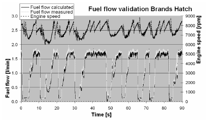
Figure 5. Fuel flow validation Brands Hatch
Results show that measured fuel flow compares well with the calculated validation data. There is a small discrepancy, mainly at full load where the measured fuel flow is slightly higher than the calculated fuel flow in most cases.
It must be noted that very basic information was used to calculate the fuel flow for validation; possible parameters that can influence the fuelling such as individual cylinder adjustments were not taken into account.
Other parameters that can affect the accuracy of the validation data are production tolerances of the injectors and inaccuracies of the applied battery correction on the opening time of the injectors.
The temperature of the fuel in the fuel flow meter was constant during the lap at 24°C and varied between 21°C at the start of a race to 24°C at the end of a race over 12 laps. Ambient temperature was approximately 16°C.
CONCLUSION
A method is proposed whereby the development goals of motorsport and road vehicles can be aligned, allowing for technology flow between the two, and improving the environmental impact of motorsport.
Fuel flow monitoring using a turbine flow meter is proposed as a preferred method for limitation of instantaneous fuel flow control as a means to encourage fuel efficiency in racing. Other investigated methods including a restricting orifice in the fuel line and specified calibrated injectors were considered and rejected due to technical inadequacies or because they would limit the competitive freedom of race teams.
Testing of a fuel flow sensor with associated temperature sensor under racing conditions showed good validation with calculated fuel flow from ECU data. Calibration of the fuel flow sensor for various fuels showed that the standard calibration for MIL-PRF-7024E can be used for a Hiperflo 250, E85 and EN590 Diesel fuel without the need to recalibrate the flow sensor. It is recommended however, that where possible a fluid with viscosity similar to that of the racing fuel is used for initial calibration of the sensor.
In order to further improve the accuracy of fuel flow measurement and to ensure consistency between measurements on different vehicles a bespoke fuel flow measurement kit has been developed and is being tested on multiple vehicles in the British Touring Car Championship. The kit consists of a specified fuel filter, fuel flow meter, temperature sensor and straight fuel pipes with specified lengths and diameters for flow conditioning. The temperature sensor has moved to a position downstream of the fuel flow meter to minimise disturbance of the fuel flow.
A project with the objective to demonstrate that it is possible to accurately control fuel flow by means of ECU recalibration and using the feedback from the fuel flow sensor is ongoing in co-operation with an ECU supplierand race engine manufacturer.
ACKNOWLEDGMENTS
The author would like to thank the Ricardo Board for providing the opportunity to write this paper and the EEMS Project Team, in particular Dr. Steve Bunkhall.
Furthermore the author would like to thank MDUK, Riches Technical Services, Tech-Speed Motorsport, Triple Eight Race Engineering Ltd., Ole Buhl Racing Ltd., Petrochem Carless and Pi Research for their continuing support. None of this would have been possible without the full support and co-operation of TOCA and the British Touring Car Championship.
REFERENCES
- On cavitation in fluid power, Timo Koivula, 2000
- Perry's Chemical Engineers' Handbook, Sixth Edition, McGraw-Hill Co., 1984.
Added to the database on 29th January 2007
| F = Volume flow |
[m3/s] |
| G = Mass flow |
[kg/s] |
| Cd = Discharge coefficient |
[-] |
| A = Flow area |
[m2] |
| p = Pressure |
[Pa] |
| ρ = Density |
[kg/m3] |
| d = Diameter |
[m] |
 |
|
 |